
Product Description
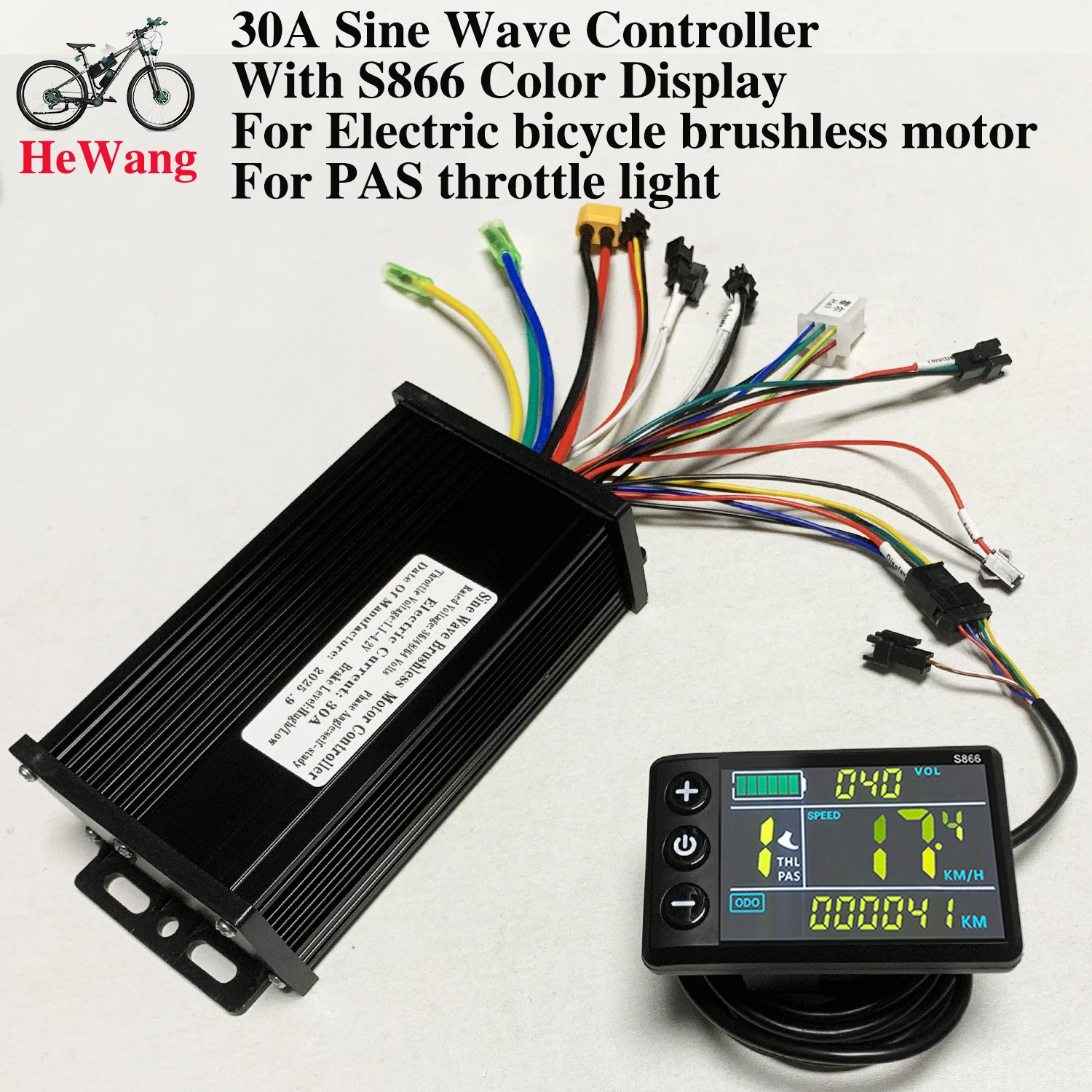
20A/30A E-Bike Sine Wave BLDC Controller with S866 Color Meter Kit 350W-1500W for UART Communication Protocol Electric Scooter 20A/30A E-Bike Sine Wave BLDC Controller with S866 Color Meter Kit 350W-1500W for UART Communication Protocol Electric Scooter
Note: If error code E10 occurs, it indicates a loose connection at the instrument panel connector. Try unplugging and replugging the cable. Refer to the video website: https://video.aliexpress-media.com/seller/play/5000376402889.mp4
Note: The 20A and 30A controllers have different sizes, you can purchase them according to your needs.
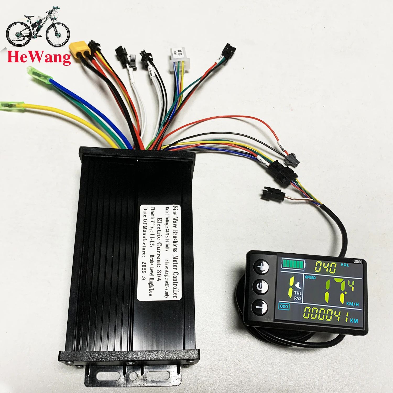
30A Black Set
Specifications: Features: This monitor is made of high-quality materials and is lightweight, rainproof, and durable. The LCD display clearly displays status and data, and the backlight allows for clear viewing in dimly lit environments. The buttons are quick and easy to use. The brushless controller is quiet and responsive to the e-bike's status. It's easy to install and use, comes with an LCD display bracket, and is compatible with 22.5mm handlebars.
You can set a power-on password and control the lights and assist. The speed range is 3, 5, or 9, with a selectable number of gears. You can choose between geared or non-geared by turning the handlebars.
Suitable for electric bicycles and scooters.
Specifications:
Material: Plastic + LCD + Metal
Color: As shown in the picture
Power: 500/750/1000W
Waterproof: Rainproof
Controller size:
Display size: Approx. 15*8.5*4cm
Weight: Approx. 500 grams
Packing list:
1 x LCD display
1 x controller
Note:
Each cable is marked with different colors for different purposes.
Red: Positive power
Black: Negative power
Yellow: Power output
Brown: Positive light
White: Negative light
Blue: Indicator light signal
Green: Signal reception
 Note:
Note:
Each cable is marked with different colors for different purposes.
Red: Positive power
Black: Negative power
Yellow: Power output
Brown: Positive light
White: Negative light
Blue: Indicator light signal
Green: Signal reception
Note:
1. The product power is set to 8 at the factory, which basically corresponds to most split superchargers on the market. If the customer uses an integrated supercharger, please set it to 12.
2. P13 in the manual is the power setting of the product. If the supercharger is incompatible, the customer needs to adjust it to 8 or 12.
3. Please note that the controller model is sent randomly. Please confirm whether you are satisfied before placing an order.
How to use: After getting the product, please be sure to align the phase first: plug in the smart identification line and identify the motor. The identification line is two green lines. After plugging in, pay attention to suspend the car, and the motor will run automatically. At this time, if the direction of rotation of the motor is correct, run for 10 to 15 seconds, disconnect the identification line, if the direction is opposite, disconnect the identification line and plug it back, the motor direction will change to forward, run for another 10 to 15 seconds, disconnect the identification line, and the motor direction will change to forward. Run for another 10-15 seconds, disconnect the identification line, and the motor direction will change to forward. Run for another 10-15 seconds, disconnect the identification line, and it's done. After the identification is completed, the identification line remains disconnected, do not plug it back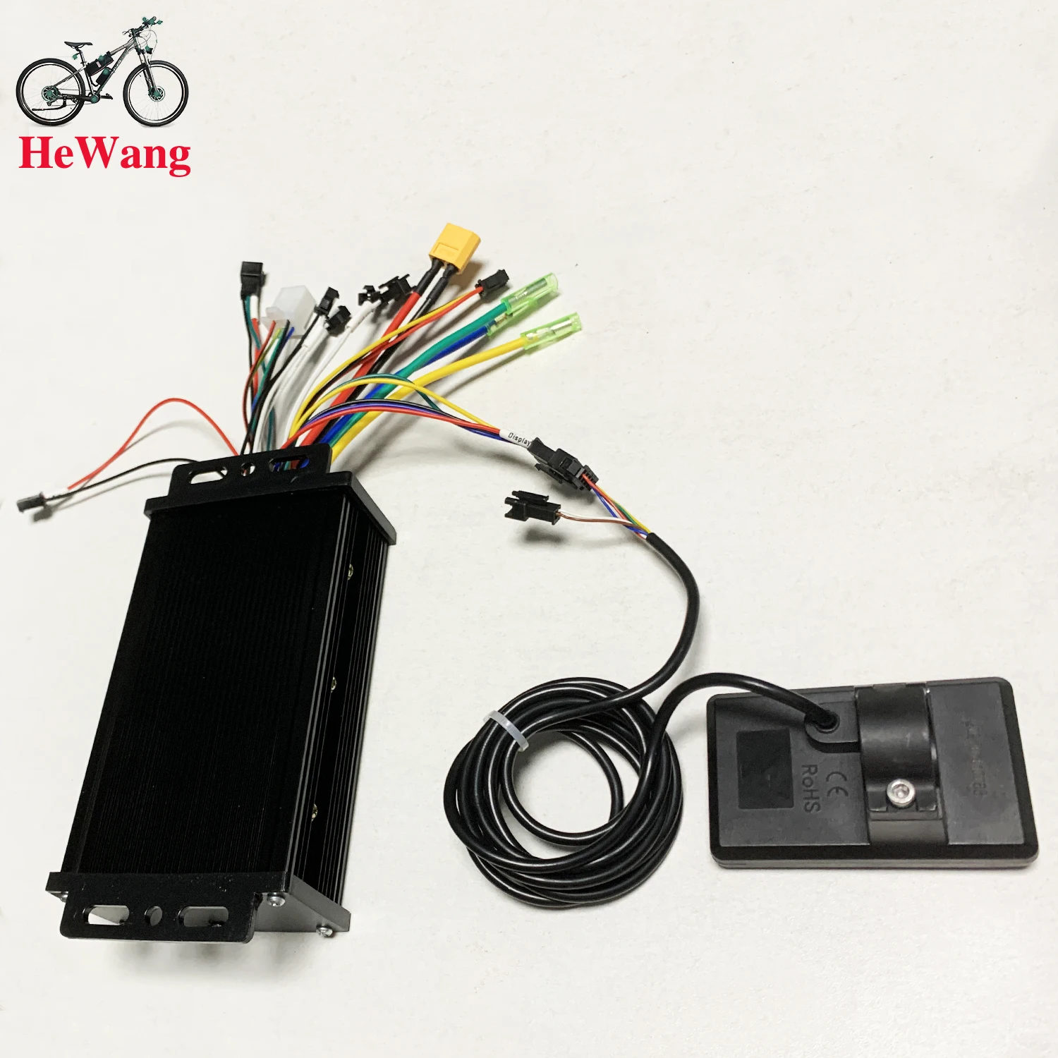 LCD Setting Parameters & Error Code Explanation
Decimal Fault Codes
E00: Normal status
E01.
E02: Brake
E03: PAS sensor fault
E04: 6KM/H cruise mode
E05: Real-time cruise
E06: Battery undervoltage
E07: Motor failure
E08: throttle fault
E09: Controller failure
E10: Communication signal reception failure
E11: Communication signal transmission fault
E12: BMS communication fault
E13: Headlight fault
How to enter Setup Mode
Long press the + and - buttons for 3-5 seconds after switching on the computer to enter the setting mode, the parameters will blink.
Short press M button to switch parameters, press + and - buttons to select parameters.
Parameter introduction
P00: Restore factory setting
P01: Backlight Brightness
P02: Mileage unit
P03: Voltage selection
P04: Sleep Time
P05: PAS Gear
P06: Wheel Diameter
P07: Speed Magnet
P08: Speed Limit
P09: Zero Start Non-Zero Start
P10: Drive mode setting, 0: PAS drive, 1: throttle drive, 2: PAS and throttle drive
P11: PAS sensitivity setting
P12: PAS start strength setting
P13: PAS magnet disc type setting
P14: Current Limit Setting
P15-16-17-18-19: Functions not yet opened, please ignore do not set 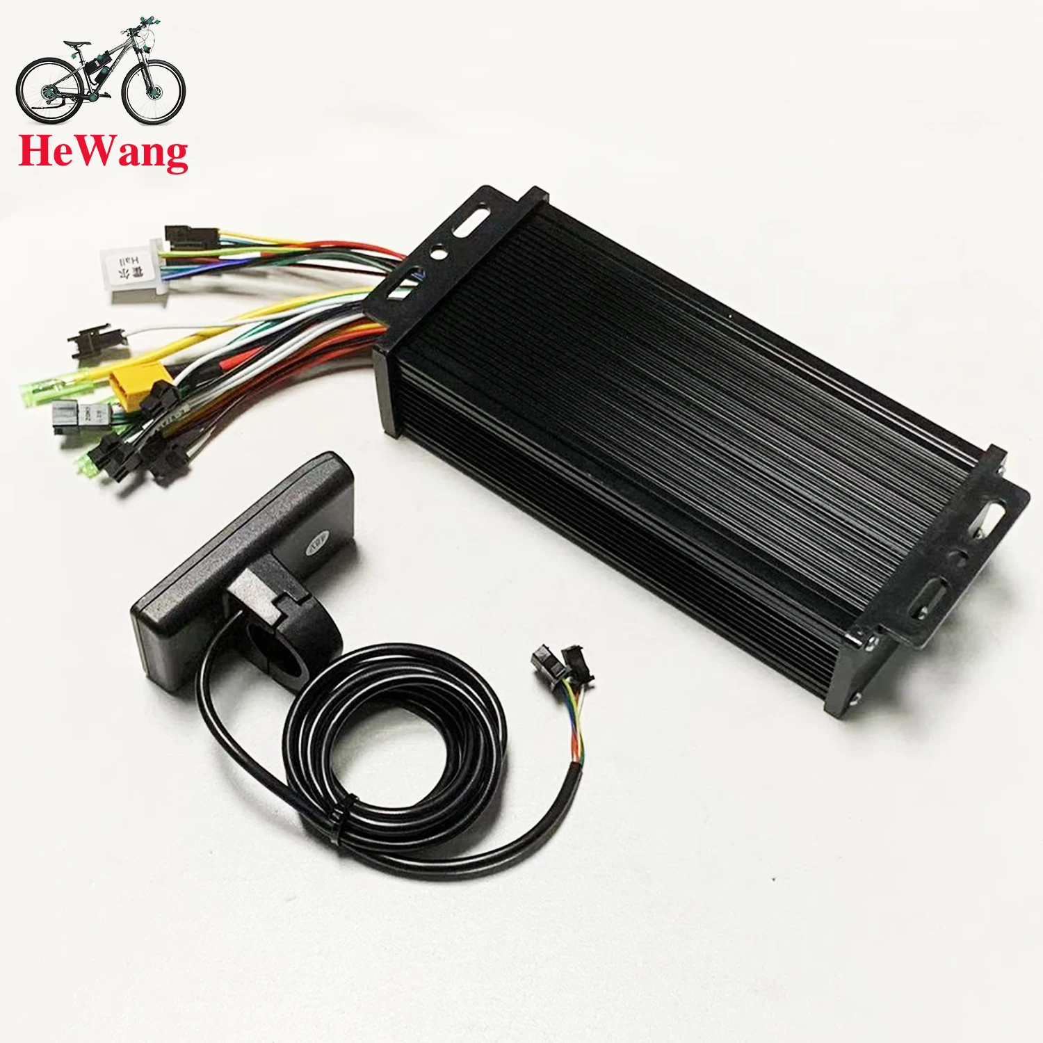 Controller Introduction
This controller is FCO sine wave design for brushless motor with hall sensor.
Brushless Hall motors are 3+5 wire or 3+6 wire, these two types of motors are best suited for Forever FOC controllers.
This controller is suitable for electric scooters as well as electric bikes, it is very compatible and designed for modification users and repair shops.
This controller has self-learning design, when you install it for the first time, there may be motor jitter, this is normal because the controller doesn't detect your motor parameter, you can short the self-learning wire for 5 seconds, the controller will automatically check your motor parameter and auto-compatible.
The advantage of this design is that the controller is compatible with almost all brushless motors. Many single mode sine wave controllers on the market do not have self-learning wires, and this controller is designed with self-learning motors to perfectly solve this problem that bothers users.
Please don't need to worry if your motor drives in reverse direction after initial installation, this is normal, you can short connect the self-learning wire to change the initial direction of the motor.
If you want accurate LCD speed display, you can enter LCD setting mode and set your motor wheel diameter in P06 in inch.
Set the speed magnet in P07, normally you can set it to 23,.
After setting P06 and P07, you can test the real time speed with map navigation APP, if the LCD display speed is bigger than the navigation display speed, then you can reduce the parameter of P07 to lower the speed display ratio.
If the LCD display speed is less than the navigation display speed, you can increase the parameter in P07 to increase the speed display ratio. After finding the exact speed that suits you in this way, you will see the LCD displaying the exact speed.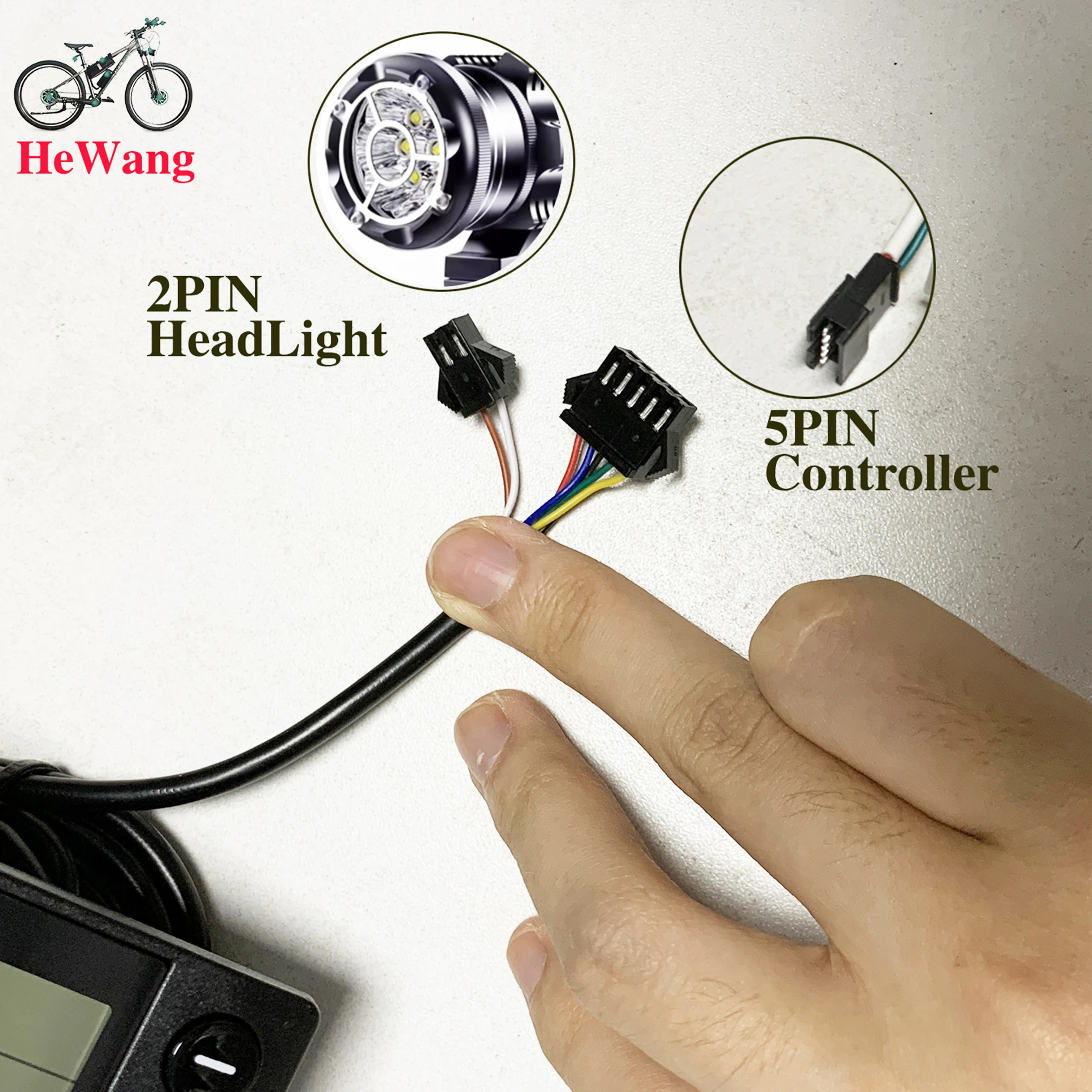
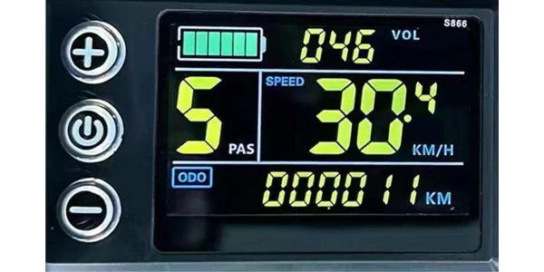
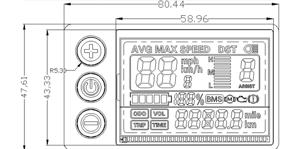
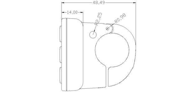 Front View Side View2. Operating Voltage and Connectionsa. Operating Voltage: DC24V / 36V / 48V (set by the display menu). Otheroperating voltage can be customized.b. Connectors:Standard Connector Type
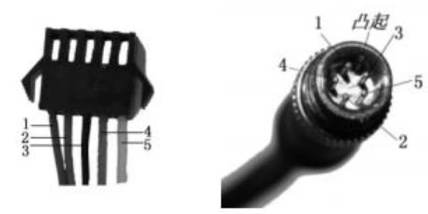 Controller Connector Display Output Connector Coupling Input ConnectorStandard Connector Arrangement Sequence No. Wire Colour Functions1 Red(VCC) Display Power Cable2 Blue(K) Controller Power On/Off Cable3 Black(GND) Display Ground Cable4 Green(RX) Display Data Receiving Wire5 Yellow(TX) Display Data Sending WireExtended FunctionsLight: Brown (DD): The positive electrode of the lightWhite (GND): The negative electrode of the light.The wire color definitions of the PWM Voltage Motor Power Controller and theindependent speed sensor will be defined otherwise.*Note: Some products use waterproof connectors, whose internal wirearrangements cannot be identified from the exterior.3. Functionsa. DisplaySpeed Display PAS Level Display Battery Level DisplayError Indication Total Mileage Single MileageLight Indication Single Trip Timeb. Control and SettingsPower Switch Front Light Control 6km/h Cruise ControlReal-time Cruise Control Wheel Diameter Setting Top Speed SettingSleep Interval Setting Backlight Brightness Setting Voltage Level Settingc. Communications Protocol: UARTDisplay Interface(Displayed for 1sec at start)
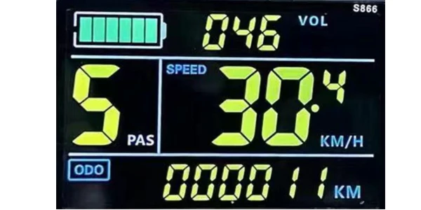 Display Interface3.1 Light
 3.2 Battery·
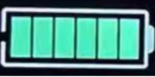 3.3 Speed Display
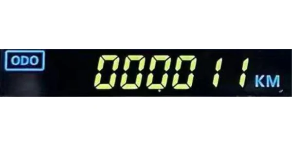
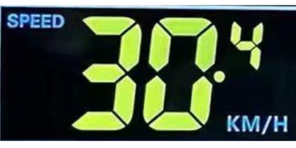 Measuring Unit: MPH or KM/HThe display will calculate the actual travelling speed based on the wheeldiameter and signal data (number of magnetic steel is needed for Hall motors).3.4 Multi-Function DisplayTotal Mileage: ODOSingle Mileage: TRIPError Code: ERRORPower: WATTStart Time: TIBattery Voltage: VOL
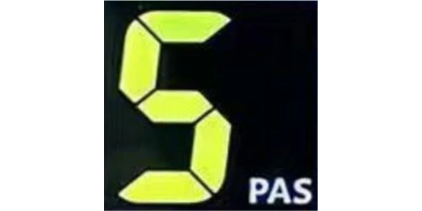
 3.5 PAS Level
 3.6 Cruise Indicator
 3.7 Error Code and IndicationsError Code(decimal)Indications Note0 Normal1 Reserved2 Brake3 PAS Sensor Failure (riding mark) Not Realized4 6km/h Cruise5 Real-Time Cruise6 Low Battery7 Motor Failure8 Throttle Failure9 Controller Failure10 Communications Receiving Failure11 Communications Sending Failure12 BMS Communications Failure13 Light Failure3.8 SettingsP01: Backlight Brightness (1: darkest; 3: brightest)P02: Mileage Unit (0: KM; 1: MILE)P03: Voltage Class 24V / 36V / 48VP04: Sleep Interval(0: never, other value means display sleep interval) Unit: minuteP05: Power Assist Gear0/3 Gear Mode: Gear 1: 2V Gear 2: 3V Gear 3: 4V1/5 Gear Mode: Gear 1: 2V Gear 2: 2.5V Gear 3: 4V Gear 4: 3.5V Gear 5:4VP06: Wheel Diameter Unit: inch Precision: 0.1P07: Magnet Steel Number (for Speed Test) Range: 1-100P08: Speed LimitRange: 0-50km/h, parameter 50 indicates no speed limit.1. Non-communications status (panel-controlled)When the current speed exceeds the speed limit, the PWM output will be shutdown; when the current speed falls to lower than the speed limit, the PWMoutput will be activated and the driving speed will be set as the current speed ±1km/h (only applies to assist power speed, not applicable to the handlebarspeed).2. Communications status (controller-controlled)The driving speed will be kept constant as the limited value.Error Value: ±1km/h (applicable to both the assist power/handlebar speed)Note: The above-mentioned values are measured by metric unit (kilometers).When the measuring unit is switched to imperial unit (mile), the speed value displayed on the panel will be automatically switched to corresponding imperialunit, however the speed limit value in the imperial unit interface won’t changeaccordingly.P09: Direct Start / Kick-to-Start Setting0: Direct Start1: Kick-to-StartP10: Drive Mode Setting0: Power Assist – The specific gear of the assist drive decides the assistpower value. In this status the handlebar does not work.1: Electric Drive – The vehicle is driven by the handlebar. In this status thepower gear does not work.2: Power Assist + Electric Drive – Electric drive does not work in zero-startstatus.P11: Power Assist Sensitivity Range: 1-24P12: Power Assist Starting Intensity Range: 0-5P13: Power Magnet Steel Number 5 / 8 / 12pcsP14: Current Limit Value: 12A by default; Range: 1-20AP15: UnspecifiedP16: ODO Zero-OutLong press the up key for 5 seconds and ODO value will be erased.Note: Due to product upgrade, the product you purchased may beslightly different from the descriptions in this user manual, and thiswon’t affect normal usage.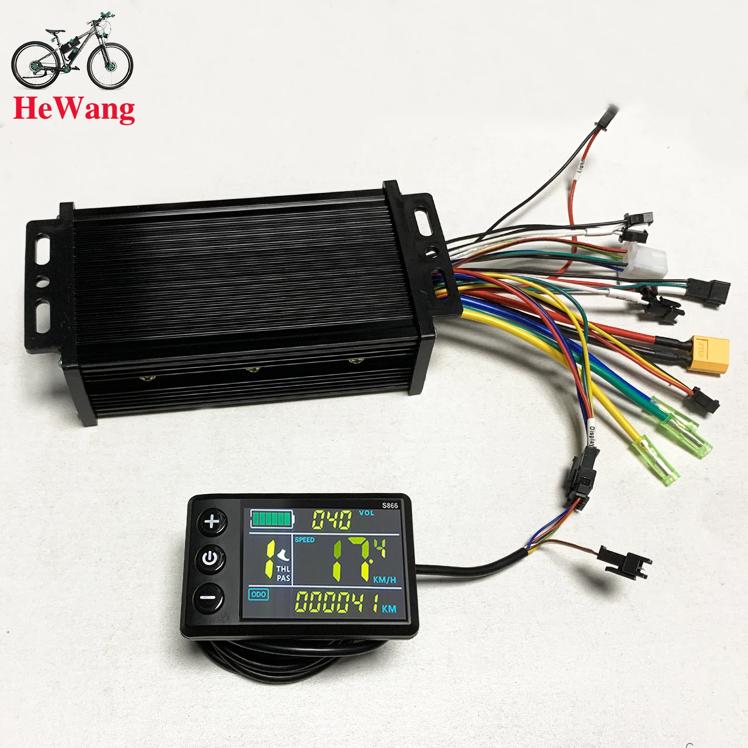
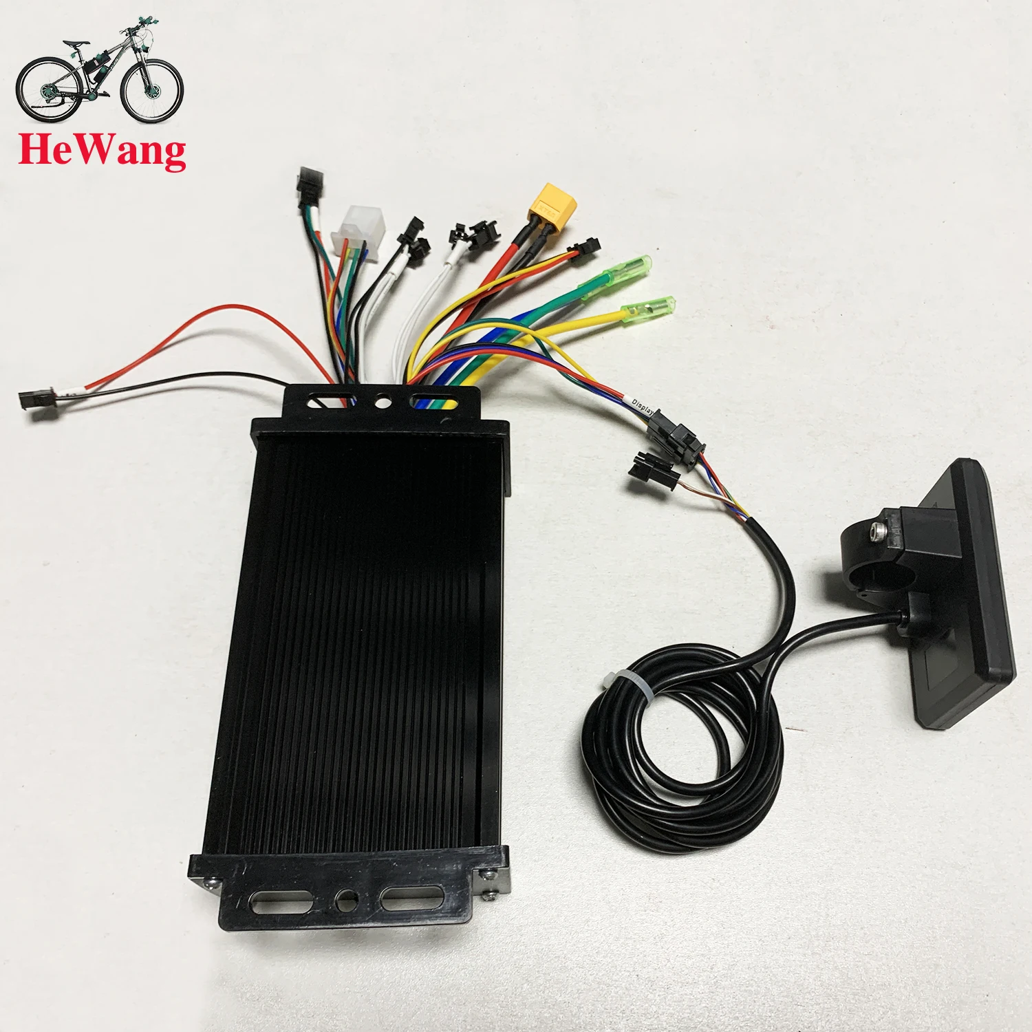
 20A Black Set
The LCD display can clearly display status and data, the backlight allows you to view the screen clearly in a dim environment, and the key operation is quick and easy to use.
The controller is a brushless controller, which works quietly and reacts sensitively to the status of the e-bike.
Easy to install and use, equipped with an LCD display bracket, suitable for 22.5mm handlebars.
You can set the power-on password, control the lights, and assist. The speed is divided into 3/5/9 gears, and the number of gears is optional. You can choose to divide or not divide the gears by turning the handle.
Suitable for electric bicycles and scooters.
Specifications:
Material: Plastic + LCD + Metal
Color: As shown in the picture
Power: 250W/350W
Waterproof: Rainproof
Controller size: Approx. 10x 7x 3.5 cm/3.94 x 2.76 x 1.38 inches
Display size: Approx. 8 x 5 cm/3.15 x 1.97 inches
Weight: Approx. 332 grams
Packing list:
1 x LCD display
1 x controller
Note:
Each cable is marked with different colors for different purposes.
Red (VCC) instrument power line
Blue (K) controller power control line
Black (GND) instrument ground line
Green (RX) instrument data receiving line
Yellow (TX) instrument data sending line
Note:
1. The product power is set to 8 at the factory, which basically corresponds to most split superchargers on the market. If the customer uses an integrated supercharger, please set it to 12.
2. P13 in the manual is the power setting of the product. If the supercharger is incompatible, the customer needs to adjust it to 8 or 12.
3. Please note that the controller model is sent randomly. Please confirm whether you are satisfied before placing an order.
How to use: After getting the product, please be sure to align the phase first: plug in the smart identification line and identify the motor. The identification line is two green lines. After plugging in, pay attention to suspend the car, and the motor will run automatically. At this time, if the direction of rotation of the motor is correct, run for 10 to 15 seconds, disconnect the identification line, if the direction is opposite, disconnect the identification line and plug it back, the motor direction will change to forward, run for another 10 to 15 seconds, disconnect the identification line, and the motor direction will change to forward. Run for another 10-15 seconds, disconnect the identification line, and the motor direction will change to forward. Run for another 10-15 seconds, disconnect the identification line, and it's done. After the identification is completed, the identification line remains disconnected, do not plug it back
Package List:
1 x LCD Display1 x ControllerWorking voltage and wiring method
1. Working voltage: DC24V, 36V, 48V compatible with other voltages can be customized,
2. Wiring method:
Note: The leads of some products use waterproof connectors, and users cannot see the lead color in the harness. Function description:
Function:
1. Display function
Speed display, power indication, fault prompt, total mileage, single mileage2. Control and setting function
Power switch control, wheel diameter setting, idle automatic sleep time setting, backlight brightness setting, startup mode setting, drive mode setting, voltage level setting, controller current limit value setting, 3. Communication protocol: UART All contents of the display screen (full display within 1S after power on)
Display content introduction
3.1 Battery power and BMS remaining power display
3.2 Multi-function display area
Total mileage 0D0, single mileage TRIP (unit: mile, km), single power-on time TIME, battery voltage VOL, DST: endurance mileage
3.3 Speed display area
AVG: average speed, MAX: maximum speed, SPEED: current speed; unit Mp/h, km/h speed signal is taken from the Hall signal in the motor and sent to the instrument through the controller, (time of a single Hall cycle, unit: 1MS) The instrument will calculate the actual speed based on the wheel diameter and signal data (the motor Hall also needs to set the number of magnetic steels),
3.4 Vehicle power gear adjustment, 0-9 gear digital display and gear bar display;
3.5 Vehicle status display area
Motor fault;: Fault;: Brake prompt;: Headlight on prompt:
3.6 Vehicle status code table:
Fault code (decimal) Fault status Remarks
0 Normal state
1 Reserved
2 Brake
3 Power sensor fault (riding sign) Not implemented here
4 6KM/H cruise
Settings
P01: Backlight brightness, level 1 is the darkest, level 3 is the brightest;
P02: Mileage unit, 0: KM; 1: MILE; P02:
P03: Voltage level: 24V, 36V, 48V;
P04: Sleep time: 0, no sleep; other numbers are sleep time, range: 1-60; unit: minutes
P05: Power gear: 0, 3 gear mode:
1, 5 gear mode:
P06: Wheel diameter: unit, inch; accuracy: 0.1;
This parameter is related to the speed displayed by the instrument and needs to be entered correctly;
P07: Number of speed magnets: range: 1-100:
This parameter is related to the speed displayed by the instrument and needs to be entered correctly;
If it is an ordinary hub motor, enter the number of magnets directly;
If it is a high-speed motor, you also need to calculate the reduction ratio, input data = number of magnets x reduction ratio;
For example: the number of motor magnets is 20, the reduction ratio is 4.3: the input data is: 86=20x4.3
P08: speed limit: range 0-100km/h, 100 means no speed limit
The input data here indicates the maximum operating speed of the vehicle: for example, input 25, which means that the maximum operating speed of the vehicle will not exceed 25km/h; the driving speed is maintained at the set value,
Error: 1km/h; (both the power assist and the handlebar are limited)
Note: The value here is based on kilometers. When the unit setting is converted from kilometers to miles, the speed value on the display interface will automatically be converted to the correct mile value, but the speed limit value set in this menu under the mile interface will not be converted, and it is inconsistent with the actual displayed mile speed limit value;Working voltage and wiring method
1. Working voltage: DC24V, 36V, 48V compatible with other voltages can be customized,
2. Wiring method:
Note: The leads of some products use waterproof connectors, and users cannot see the lead color in the harness. Function description:
Function:
1. Display function
Speed display, power indication, fault prompt, total mileage, single mileage2. Control and setting function
Power switch control, wheel diameter setting, idle automatic sleep time setting, backlight brightness setting, startup mode setting, drive mode setting, voltage level setting, controller current limit value setting, 3. Communication protocol: UART All contents of the display screen (full display within 1S after power on)
Display content introduction
3.1 Battery power and BMS remaining power display
3.2 Multi-function display area
Total mileage 0D0, single mileage TRIP (unit: mile, km), single power-on time TIME, battery voltage VOL, DST: endurance mileage
3.3 Speed display area
AVG: average speed, MAX: maximum speed, SPEED: current speed; unit Mp/h, km/h speed signal is taken from the Hall signal in the motor and sent to the instrument through the controller, (time of a single Hall cycle, unit: 1MS) The instrument will calculate the actual speed based on the wheel diameter and signal data (the motor Hall also needs to set the number of magnetic steels),
3.4 Vehicle power gear adjustment, 0-9 gear digital display and gear bar display;
3.5 Vehicle status display area
Motor fault;: Fault;: Brake prompt;: Headlight on prompt:
3.6 Vehicle status code table:
Fault code (decimal) Fault status Remarks
0 Normal state
1 Reserved
2 Brake
3 Power sensor fault (riding sign) Not implemented here
4 6KM/H cruise
Settings
P01: Backlight brightness, level 1 is the darkest, level 3 is the brightest;
P02: Mileage unit, 0: KM; 1: MILE; P02:
P03: Voltage level: 24V, 36V, 48V;
P04: Sleep time: 0, no sleep; other numbers are sleep time, range: 1-60; unit: minutes
P05: Power gear: 0, 3 gear mode:
1, 5 gear mode:
P06: Wheel diameter: unit, inch; accuracy: 0.1;
This parameter is related to the speed displayed by the instrument and needs to be entered correctly;
P07: Number of speed magnets: range: 1-100:
This parameter is related to the speed displayed by the instrument and needs to be entered correctly;
If it is an ordinary hub motor, enter the number of magnets directly;
If it is a high-speed motor, you also need to calculate the reduction ratio, input data = number of magnets x reduction ratio;
For example: the number of motor magnets is 20, the reduction ratio is 4.3: the input data is: 86=20x4.3
P08: speed limit: range 0-100km/h, 100 means no speed limit
The input data here indicates the maximum operating speed of the vehicle: for example, input 25, which means that the maximum operating speed of the vehicle will not exceed 25km/h; the driving speed is maintained at the set value,
Error: 1km/h; (both the power assist and the handlebar are limited)
Note: The value here is based on kilometers. When the unit setting is converted from kilometers to miles, the speed value on the display interface will automatically be converted to the correct mile value, but the speed limit value set in this menu under the mile interface will not be converted, and it is inconsistent with the actual displayed mile speed limit value;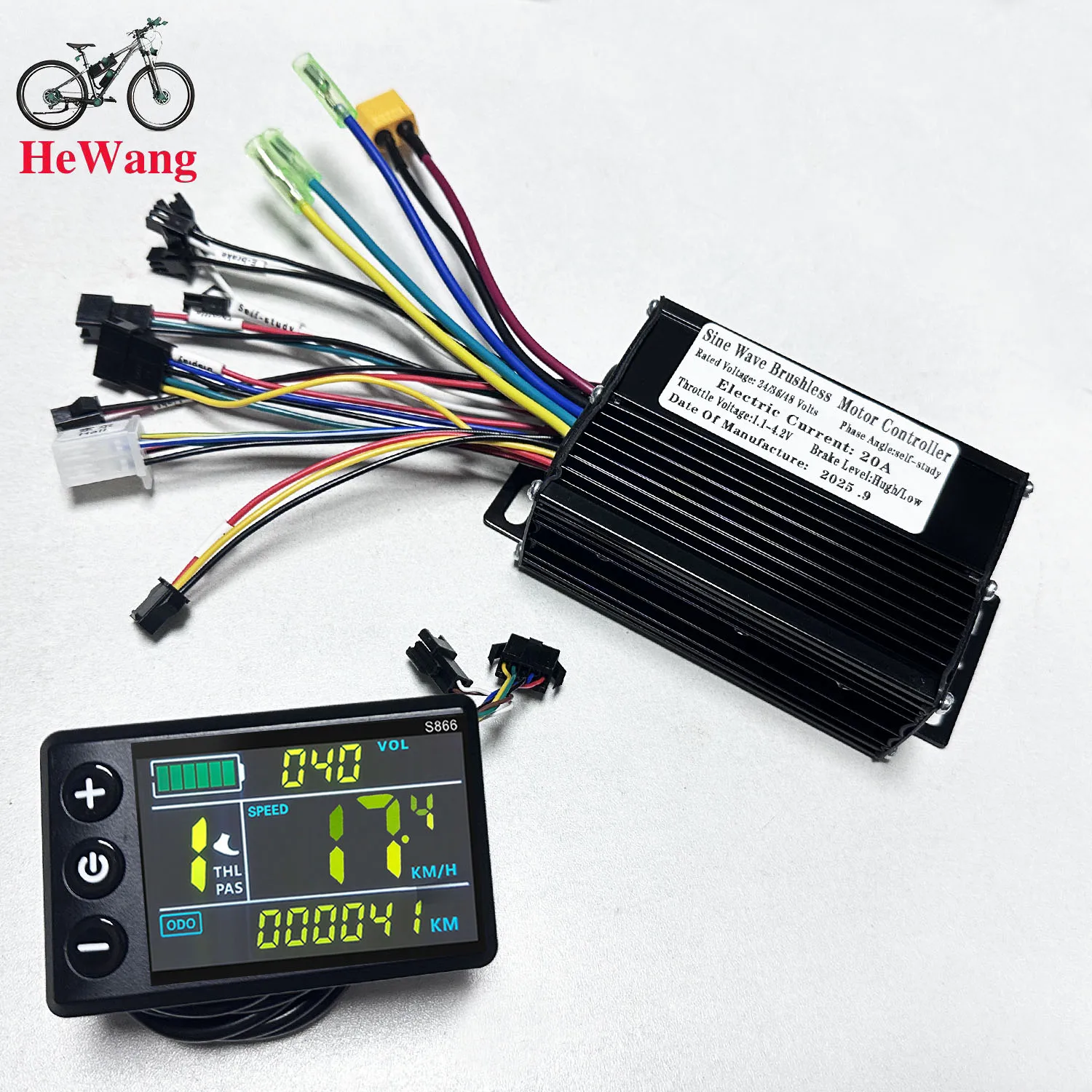
30A:
1.Motor cable 2.Motor cable 3.Motor cable
4.Power cable
5.Self-learning
6.hall
7.No.2 protocol LCD display
8.Electronic brake
9.Throttle
10.P.A.S
11.Light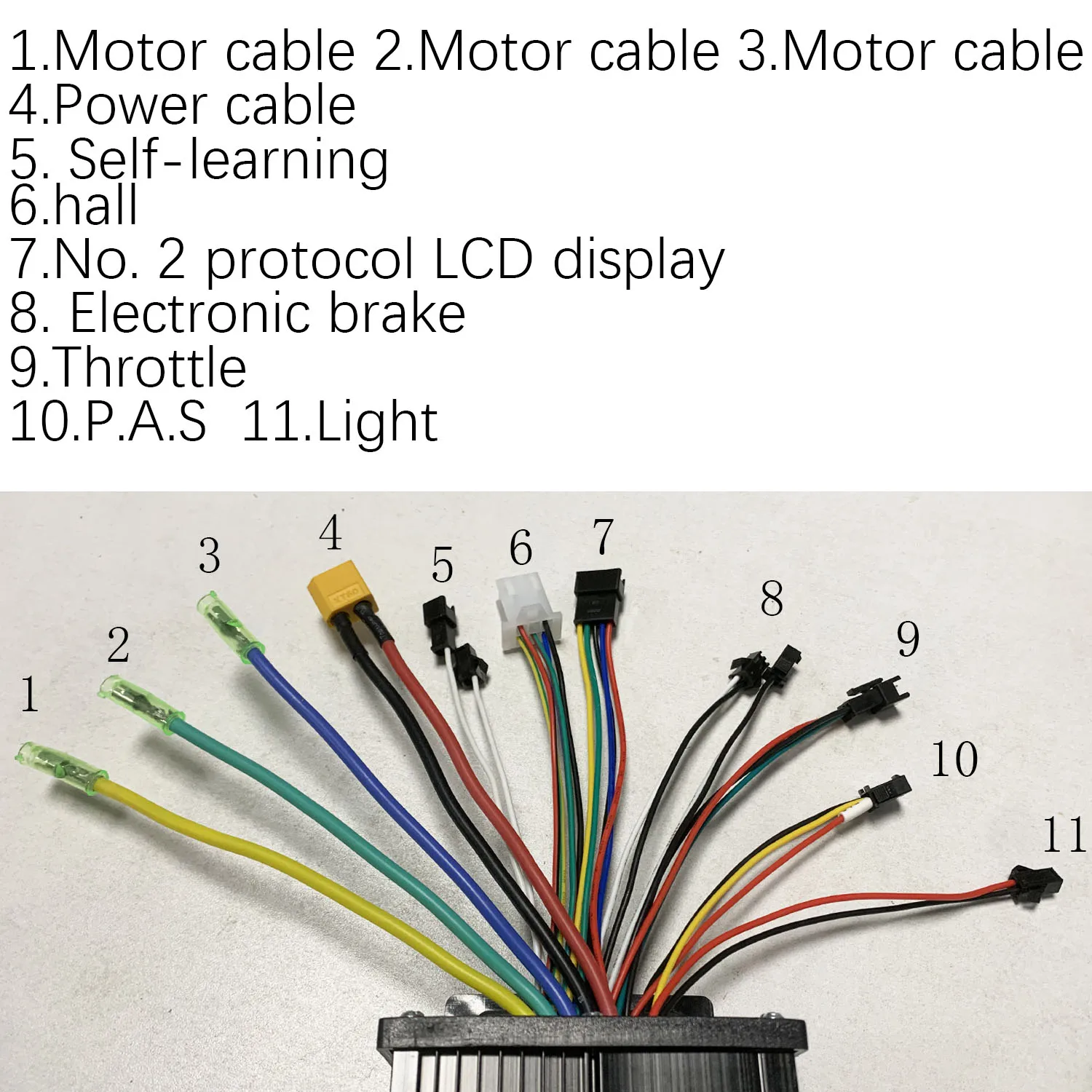
About Prime Living
Prime Living is a Canadian online store offering a carefully selected range of quality products for home, automotive, tools, outdoor living, electronics and more.
We are committed to fast order processing, secure packaging and reliable tracked shipping to provide an excellent shopping experience.
Shipping policy
We carefully handle each order to ensure your package arrives quickly and safely. Please note that factors such as weather, postal traffic, or carrier performance may occasionally cause delays beyond our control.
We provide free shipping and dispatch all orders within 2 business days of payment, often sooner. All shipments are sent via international express air shipping, with a tracking number provided so you can follow your order every step of the way.
. Please provide a physical address, as we do not ship to P.O. Boxes.
Returns
Your satisfaction is important to us. Hexlight offers a 14-day Free return policy: if you are not fully satisfied with your purchase, you may request either a full refund or an exchange. All return shipping costs are fully covered by us.
Condition
Brand New
Shipping
This item is shipped directly from our supplier in China with tracking.